Supplier of control and measuring instruments in Latvia, Estonia and Lithuania. Worldwide delivery
Supplier of control and measuring instruments in Latvia, Estonia and Lithuania. Worldwide delivery
Thermography is a non-invasive inspection technique that can be performed remotely over large areas and provides immediate feedback; because of these characteristics, it has long been used to detect anomalies in photovoltaic panels.
Thermal camera inspections can be conducted under normal plant operating conditions, during testing at scheduled intervals, or during periodic activities, e.g., panel cleaning.
The first important step in obtaining good results is to choose the most appropriate instrument according to the activities to be performed. The choice of the most suitable thermal imaging camera for PV applications is mainly constrained by the distance from which one can work safely while obtaining sufficiently detailed images. The farther one moves away from the surfaces to be inspected, the higher the resolution of the thermal camera must be in terms of the number of Pixels and low IFOV.
What is IFOV? IFOV (Instantaneous Field Of View) indicates the size of the single pixel of the thermal image at a certain distance; the smaller its value, the more detailed the image. IFOV is generally expressed in mrad (milliradians); for example, the projection of one pixel of a thermal camera with IFOV equal to 1 mrad at a distance of one meter covers the area of 1mm on each side.
Calculations based on the geometric parameters of the system are used to determine the required working distance and equipment compliance. According to the IEC TS 62446-3 technical specification, a key requirement is that each individual photoelectric cell must have at least 5x5 pixels of thermal imaging to ensure sufficient resolution.
For example, to determine the maximum viewing distance of a panel with 15x15 cm cells using a Hikmicro M20 thermal imager, a calculation is performed taking into account the size of the required spot (5x5 pixels per cell). The result is the maximum distance, for example 17.25 m, as well as the field of view of the entire image at this distance, which is 7.81 m horizontally and 5.81 m vertically.
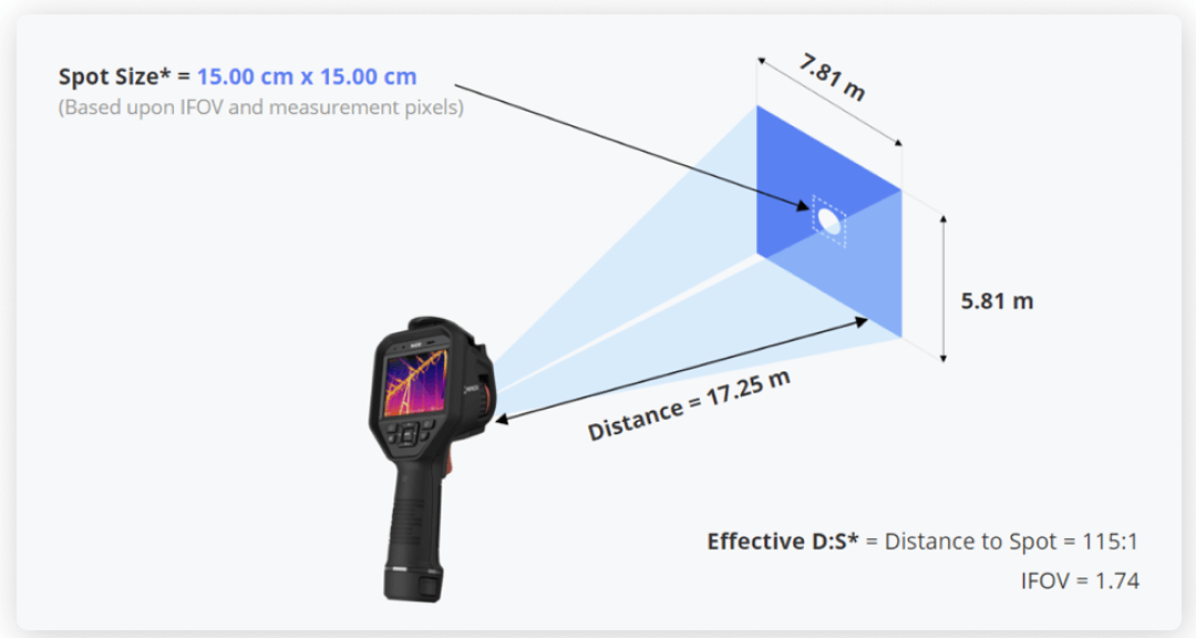
Therefore, it is necessary to always work within the maximum distance that ensures that the thermal imaging camera can cover each cell with at least 5x5 pixels.
IEC 62446 defines the procedures for inspecting PV panels with a thermal imaging camera and the weather conditions within which to conduct inspections are also given in addition to the technical characteristics of the thermal imaging cameras (all Hikmicro thermal imaging cameras have the required minimum characteristics).
When conducting inspections on photovoltaic panels, it is always a good idea to consider the following:
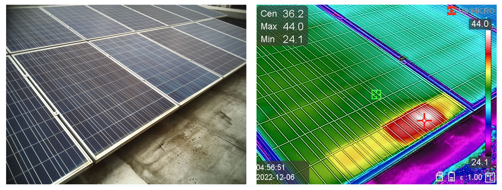
Some defects that can be detected on the panels are: